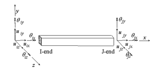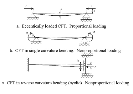
Verification of Macro Model:
Proportional Loading, Biaxial Bending,
Moderate Length Column, Normal Strength Concrete
|
|
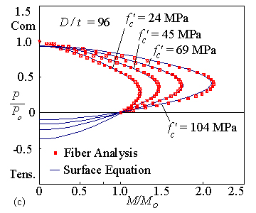
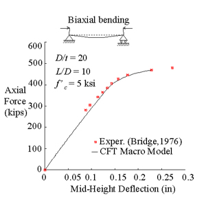
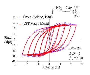
Verification of Macro Model:
Proportional Loading, Slender Column,
High Strength Concrete
|
| |
|
|
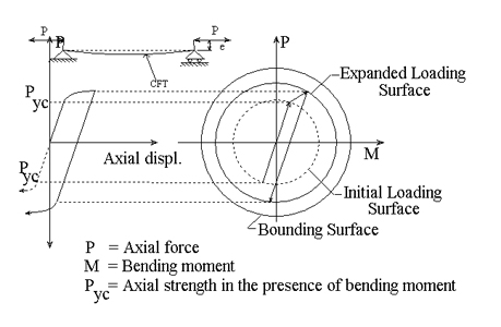
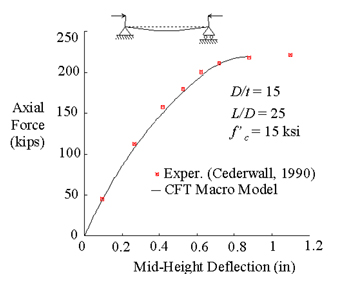
Verification of CFT Macro Model:
Nonproportional Loading, Stocky Column,
Normal Strength Concrete
|
|
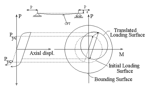
Verification of CFT Macro Model:
Nonproportional Loading, Stocky Column
Normal Strength Concrete
|
| |
|
|
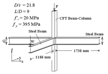
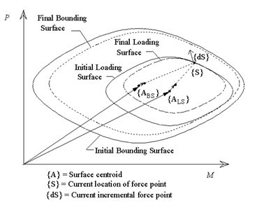
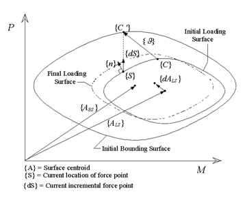
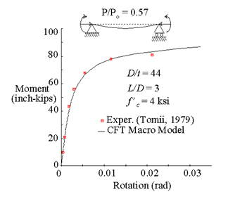
CFT Subassemblage Analysis
Verification:
Cyclic Nonproportional Loading with
Axial Force Plus Bending of CFT Beam-Column
|
|

CFT Subassemblage Analysis Verification
Analysis model, Measuring Average Shear, Q, versus
Chord Rotation, R = (D1 + D2) / L
|
|
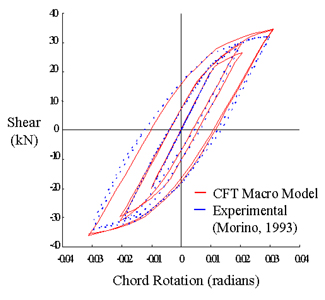
Comparison of Computational and Experimental
Results ( R versus Q) for Morino Subassemblage |
|