WATER TREATMENT DEMONSTRATION
Municipalities often use river water as a drinking water resource, but the raw water is not suitable to drink without treatment. The raw water needs to be treated by removing suspended solids and disinfecting pathogens. This demonstration illustrates four unit operations involved in treating river water.
Model Set Up
The water treatment demonstration model consists of: (a) an initial rapid mixing basin that mixes influent raw water and a coagulant (alum), (b) three coagulation-flocculation basins with gentle mixing, (c) a sedimentation basin for settling flocs, and (d) a plug-flow chlorination basin.
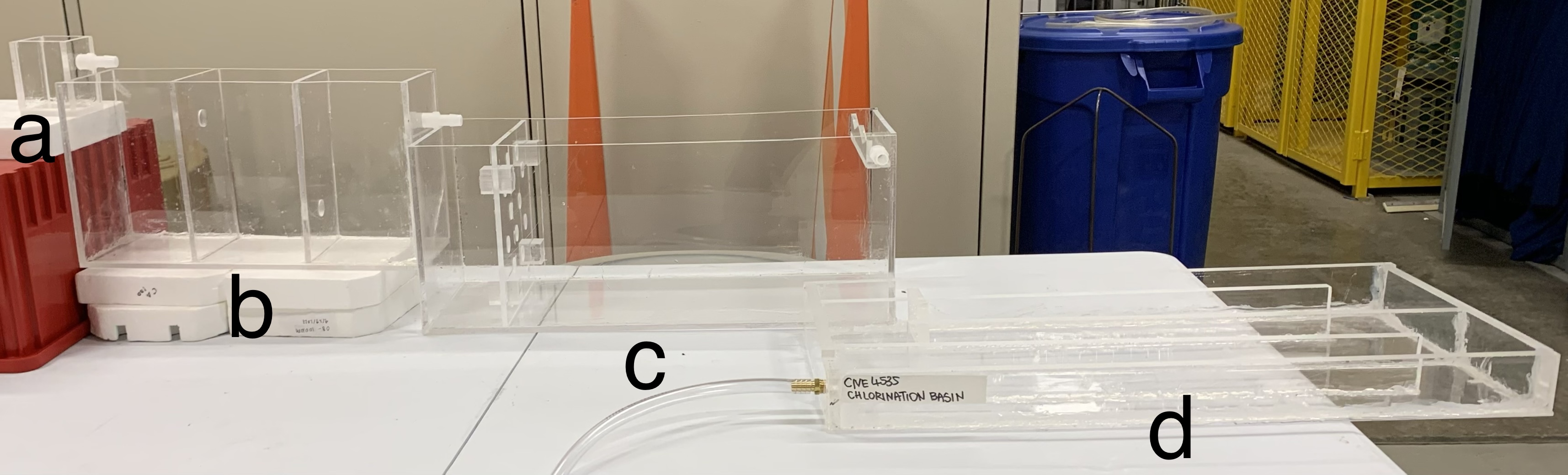
STEP 1: Mixing Basin
The influent raw water consists of a suspension of bentonite clay with a pinch of sodium bicarbonate to provide a buffer ability at a pH of 10. The raw water is pumped into the mixing basin which is stirred rapidly with a magnetic stir bar. A stream of a coagulant solution, alum (aluminum sulfate), is added, along with a stream of sodium hydroxide solution. The alum solution contains dissolved Al3+ cations, and the sodium hydroxide solution provides OH- anions to precipitate solid aluminum hydroxide (Al(OH)3) flocs.
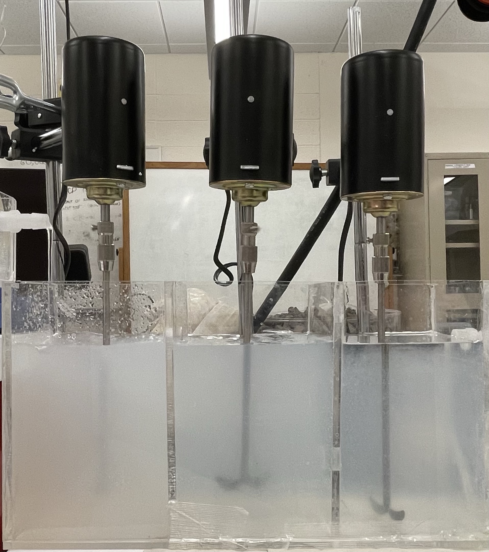
STEP 2: Coagulation-Flocculation Basin
Water from the mixing basin flows into the coagulation-flocculation basin. The motor of the first chamber is at a high speed, the second is at a medium speed, and the last is at a low speed. The faster mixing in the first basin allows thorough mixing and contact between the Al(OH)3 and the clay particles, which attach together, and the slower mixing downstream allows for the flocs to grow in size. Fluffy, white precipitants of Al(OH)3 become more readily apparant. At this point, the pH of the solution is around 5.3. Progressively, each tank of the three coagulation-flocculation basins becomes more transparent as the floc size grows.
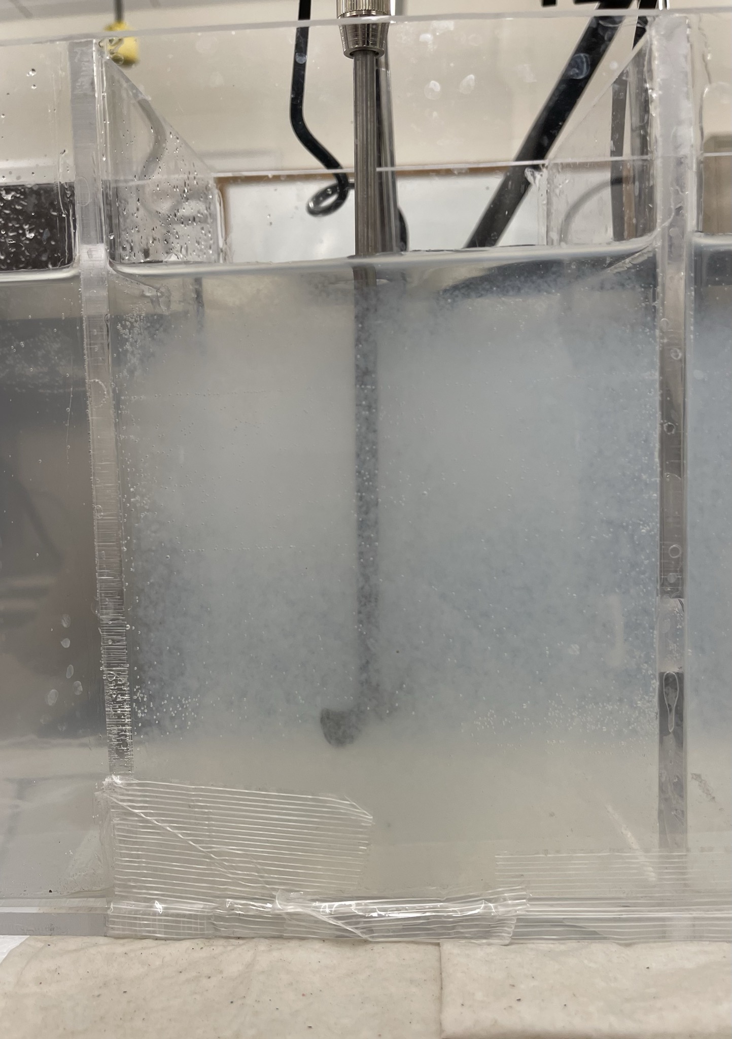
STEP 3: Sedimentation Basin
The water spills into the sedimentation basin and flows foward while the precipitants settle to the bottom. The basin dimensions are designed to slow the forward movement of water so that nearly all of the flocs have time to settle out.
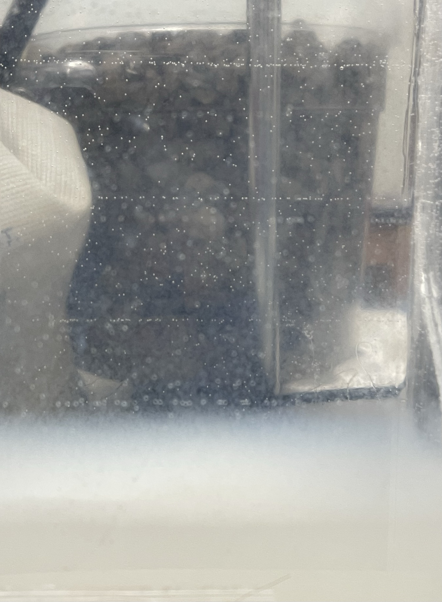
A blanket of white precipitate sludge is apparent at the bottom of the sedimentation basin.
STEP 4: Chlorination Basin
The water falls into the chlorination basin where a chlorine disinfectant solution is added to inactivate any possible bacteria, viruses, and other microbes. Chlorine is a commonly used disinfectant at drinking water treatment plants, and here a simple solution of bleach is used. The chlorine solution is dripped into the stream of treated water, and together the water flows through a snaking path which allows for the needed contact time (typically about 20 minutes) for chlorine to inactivate microorganisms prior to entrance into the distribution system.
Further discussion on the flow of water within snaking pathway style plug-flow basins can be found at our companion website hosting videos of flow regimes and reaction kinetics
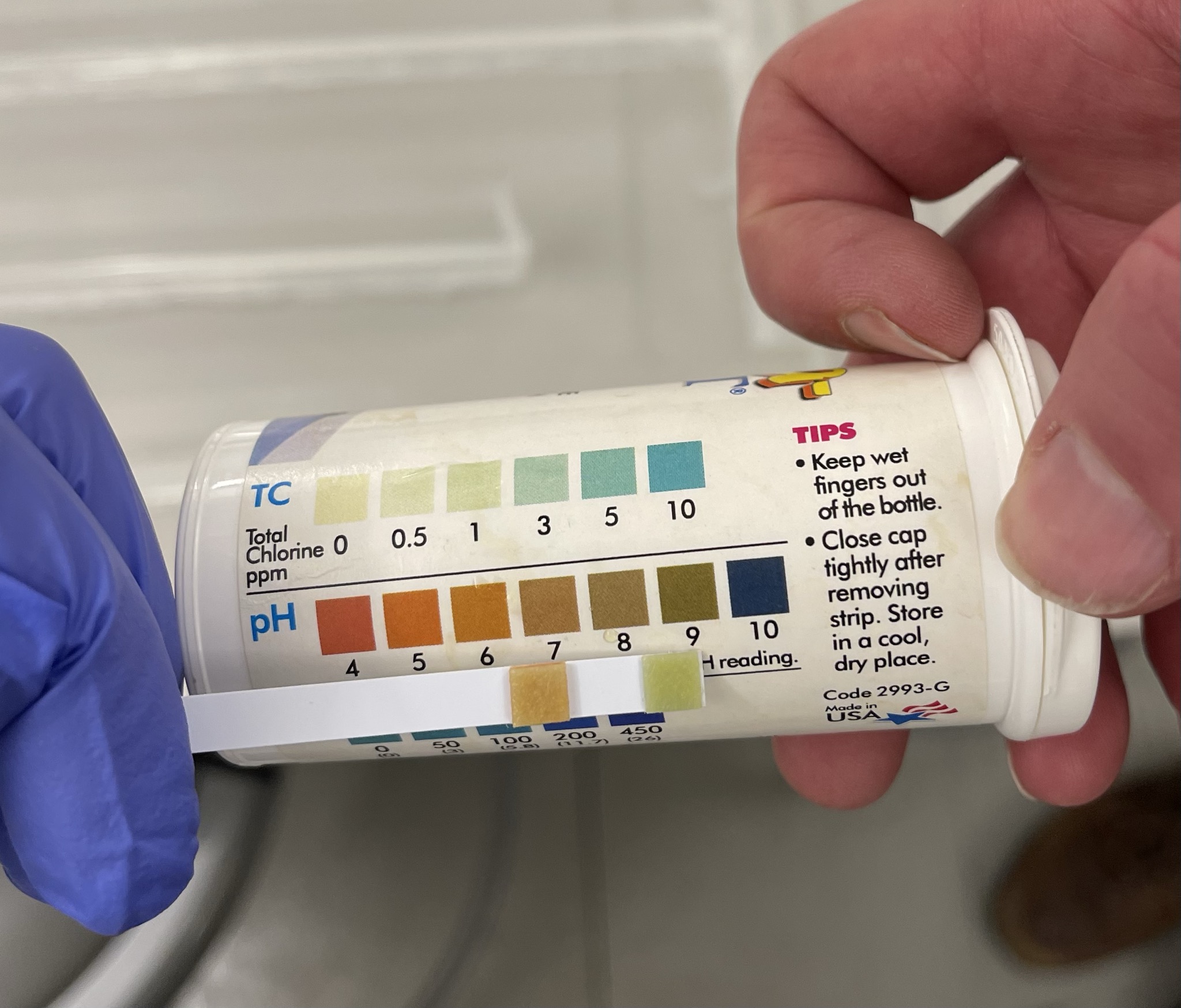
The water exiting the chlorination basin has the pH near 7, which can be checked with a pH strip.
Turbidity
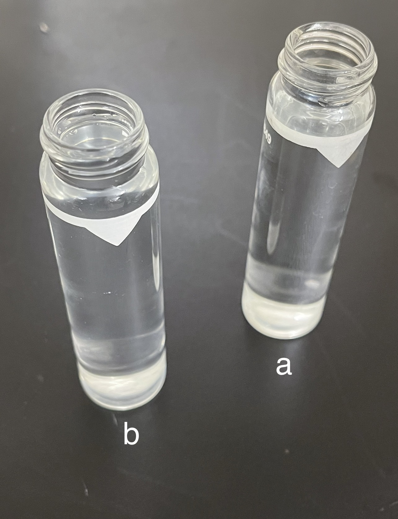
The effectiveness of the treatment system to remove the clay particles can be checked by measuring turbidity, an indication of how cloudy the water is. In the image below, (a) is the raw water solution, and (b) is the water after treatment
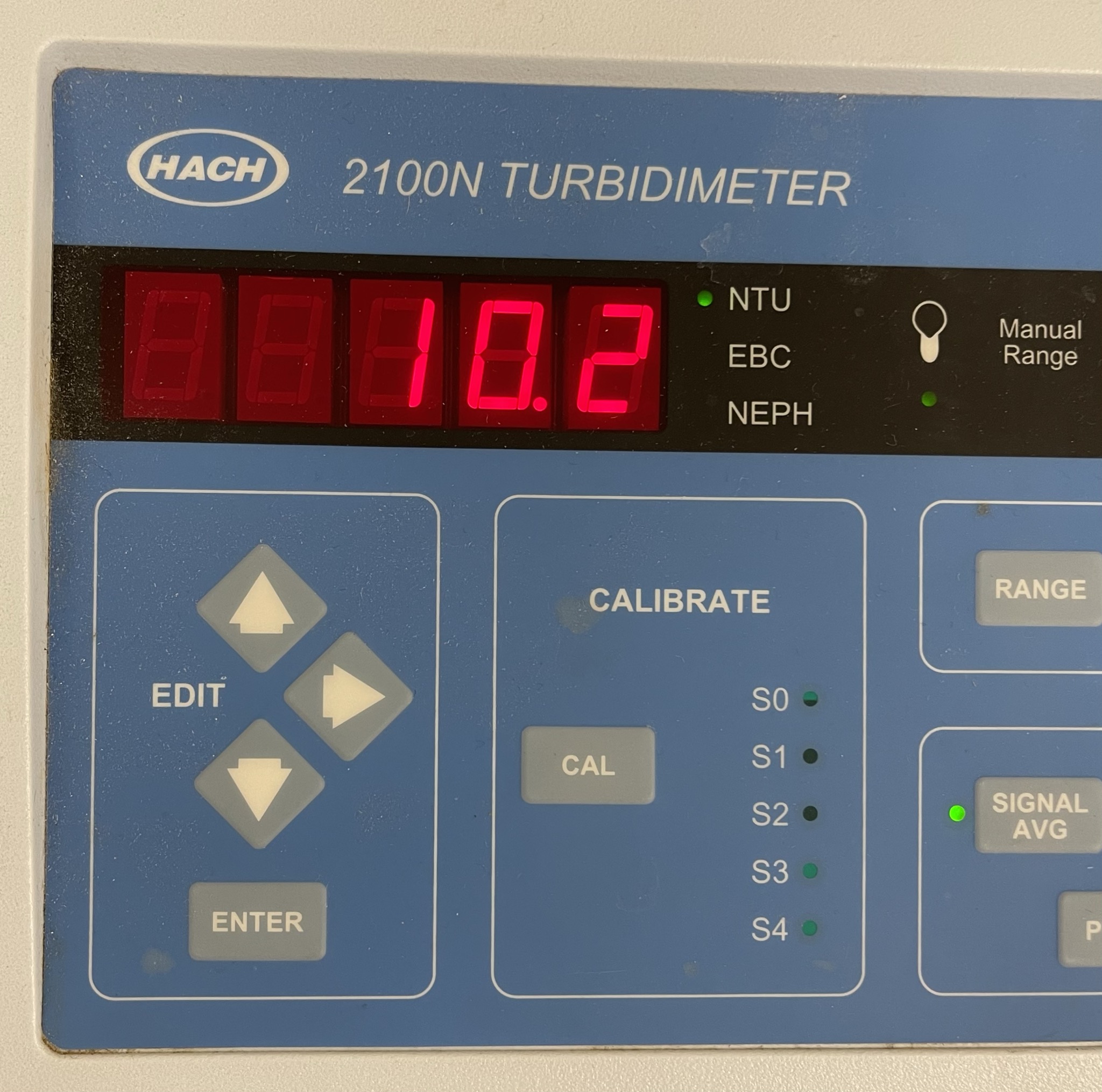
Turbidity is measured using a nephthelometer. The raw water (a) has the turbidity of 10.2 NTU.
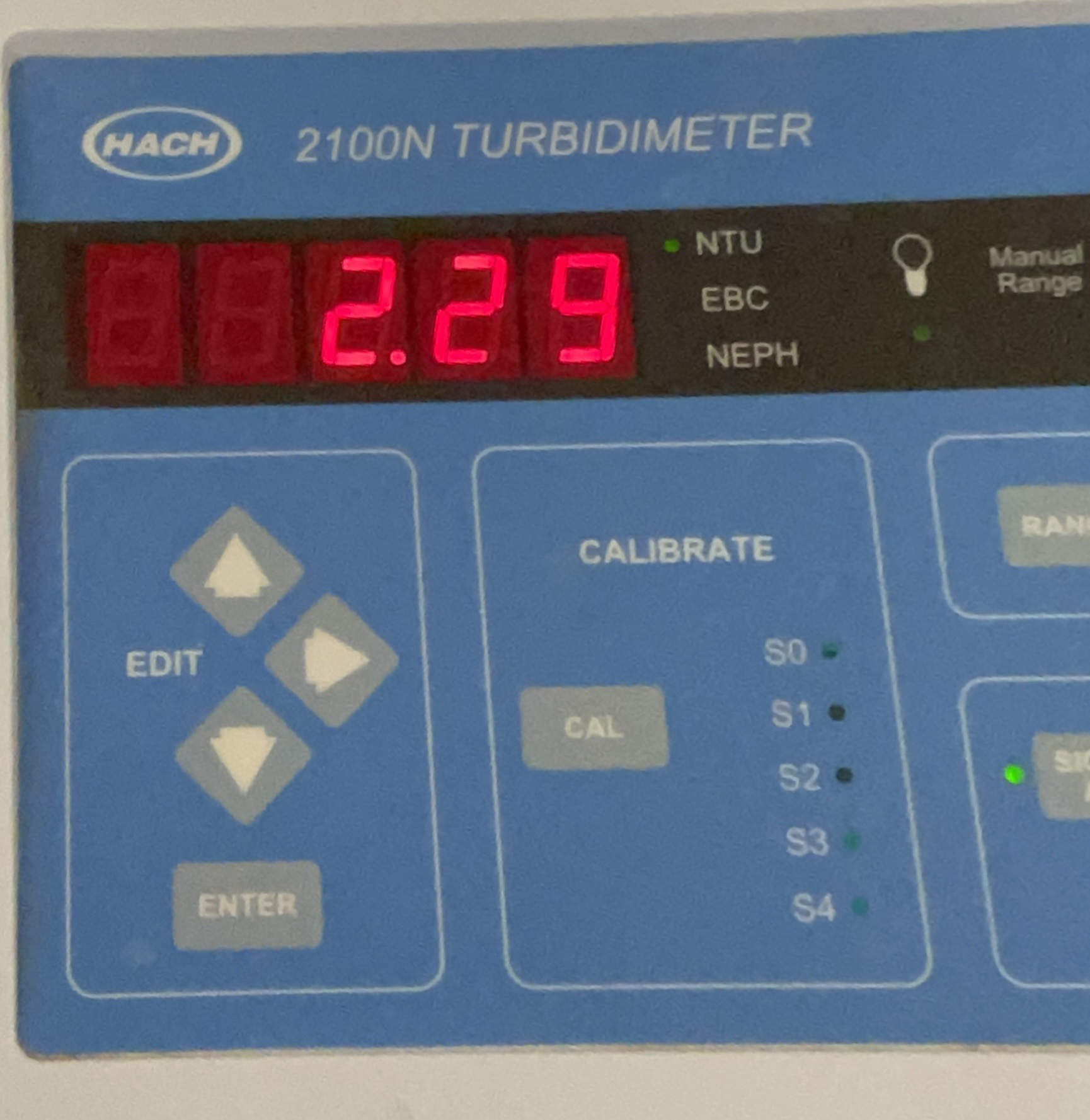
The treated water (b) has the turbidity of 2.29 NTU, which is less than the raw water. The residual NTU is less than the maximum value of 5 NTU allowed by drinking water quality regulations. If further removal of turbidity is desired, another treatment operation in the form of a sand filter could be used.
This demonstration unit was fabricated and operated by Faith Choi and supported by resources from the National Science Foundation.